
Choosing the right Power Inductors involves more than selecting the highest current rating. It requires a careful match between electrical, thermal, mechanical, and cost requirements. In practical design reviews, a compact inductor may pass bench testing but overheat inside a sealed enclosure. That difference matters. Selection should begin with the converter topology, switching frequency, peak current, ripple current, ambient temperature, and available board space. Designers should compare saturation current, RMS current, DC resistance, and impedance across frequency. These specifications describe different risks. They are not interchangeable. A component with low resistance may still saturate during a sudden load increase. A physically larger part may offer better heat dissipation but create routing or clearance problems. Small details matter.
Reliable decisions also depend on evidence beyond a single datasheet table. Experienced engineers review test conditions, tolerance ranges, core materials, insulation ratings, and thermal derating curves. A reputable manufacturer should provide consistent production data, qualification results, and clear measurement methods. Prototype testing remains essential. Measure temperature rise with a realistic load, inspect waveform distortion, and check performance after extended operation. I have seen designs fail because testing used average current instead of peak current. That mistake is easy to repeat. No selection method is perfect. Even accurate calculations can miss airflow changes, nearby heat sources, or assembly variation. A sensible design leaves margin and documents its assumptions. This guide explains how to evaluate Power Inductors with practical judgment, measurable criteria, and a willingness to revisit decisions when real hardware disagrees.
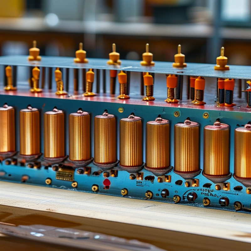
Power inductors store energy in a magnetic field and release it when a circuit needs stable current. This role makes them essential in voltage regulators, converters, battery systems, and motor controls. In a switching converter, the inductor helps smooth rapid current changes. Without it, the output voltage may show unwanted ripple, noise, or instability.
Inductance is only one part of the decision. Engineers should check saturation current, rated current, DC resistance, operating frequency, and temperature rise. A suitable inductor must handle the expected load without excessive heating. During practical testing, a part can appear acceptable at room temperature but perform poorly inside a compact enclosure. That detail is easy to miss.
Physical size also affects performance. A smaller component may save board space, yet it often offers less thermal margin. Shielded construction can reduce electromagnetic interference, especially near sensitive signal paths. However, it is not a complete solution. Layout, switching speed, and grounding still matter. Measurement is essential. Use an oscilloscope and a thermal camera when possible.
Selection involves compromise.
Engineers should compare data-sheet conditions with real operating conditions. Test the highest expected current, not only the typical load. I have found that conservative choices are often safer, but excessive margin can increase cost and board area. The best decision balances electrical performance, heat, reliability, and available space.
How to Choose the Right Power Inductors?
Choosing a power inductor starts with electrical limits, not package size. Define the converter’s maximum current, switching frequency, inductance range, ripple current, and acceptable temperature rise. The saturation current should exceed the real peak current, including startup and fault transients. A small margin matters. However, oversized margins can increase resistance, cost, and board area.
The IEA’s Electricity 2024 report estimates that data centers consumed about 460 TWh globally in 2022. It also expects demand to exceed 1,000 TWh by 2026. This pressure encourages higher power density, making copper loss and thermal performance critical. Check the DC resistance at the expected operating temperature, not only at room temperature. Core loss can rise sharply at higher frequencies. A datasheet is not the circuit.
Mechanical requirements deserve equal attention. Confirm the footprint, height, terminal strength, vibration tolerance, and clearance from heat-sensitive components. Standards such as AEC-Q200 and IPC-9592B provide useful reliability frameworks, but they cannot replace application testing. Measure temperature with the actual PCB, airflow, switching waveform, and enclosure. I have sometimes trusted calculated values too quickly. Real boards expose uneven copper, hot spots, and acoustic noise that simulations may miss. Leave room for inspection and rework. Small details become expensive later.
This representative comparison shows the typical trade-off between inductance, current capability, and DC resistance in power inductors. Higher inductance values generally provide lower ripple current but tend to have lower saturation current and higher resistance. Select an inductor by checking inductance, saturation current, temperature rise, DCR, switching frequency, and available PCB space.
How to Choose the Right Power Inductors?
Comparing Inductor Core Materials, Shapes, and Construction
Choosing a power inductor starts with operating conditions, not physical size. Check inductance, peak current, ripple current, switching frequency, and temperature rise. A part that looks adequate may saturate during a short load surge.
Ferrite cores usually provide low losses at higher switching frequencies. They suit compact converters with controlled current ripple. Powdered iron cores offer distributed air gaps and handle energy storage well. However, their core losses can increase noticeably with frequency. Metal composite cores often combine high saturation resistance with small dimensions, but their thermal behavior still requires testing. Read the full datasheet, not only the inductance value.
Shape changes electrical performance. Toroidal cores can reduce magnetic leakage and provide efficient coupling. Drum cores are economical, yet they may radiate more noise without shielding. Shielded molded inductors are useful near sensitive control circuits. Construction matters too. Wire-wound parts often deliver strong current performance, while multilayer designs save space but may carry less energy. On the bench, I check DCR with a meter and temperature with a thermocouple after a realistic load run. A practical mistake is trusting room-temperature measurements. I have made that shortcut myself. The result looked stable, but the inductor overheated after twenty minutes. Leave thermal margin, especially when airflow is limited.
| Core Material | Typical Relative Permeability | Typical Saturation Flux Density | Practical Frequency Range | Energy Storage Capability | Main Advantages | Typical Limitations | Common Power-Inductor Uses |
|---|---|---|---|---|---|---|---|
| MnZn Ferrite | Approximately 800–15,000, depending on grade and frequency | Approximately 0.35–0.50 T | About 20 kHz–1 MHz; most efficient range depends strongly on grade and temperature | Moderate; normally requires an air gap for substantial DC energy storage | Low core loss at switching frequencies, high permeability, good availability, and compact magnetic designs | Relatively low saturation flux density; permeability and losses vary with temperature and DC bias | DC-DC converters, EMI filters, output chokes, and general switching power supplies |
| NiZn Ferrite | Approximately 10–2,000, depending on grade | Approximately 0.20–0.40 T | Typically 1 MHz–300 MHz and higher for selected grades | Low to moderate; usually selected for high-frequency impedance rather than high stored energy | High electrical resistivity, low eddy-current loss, and good high-frequency performance | Lower permeability and saturation capability than many low-frequency magnetic materials | RF filters, high-frequency suppression components, and compact high-frequency inductors |
| Iron Powder | Approximately 10–100, depending on distributed-gap formulation | Approximately 0.70–1.50 T | About 10 kHz–500 kHz, with losses increasing at higher frequency | High; distributed air gaps provide good DC-bias tolerance and gradual saturation | High saturation capability, robust DC-bias performance, and useful energy storage | Higher core loss than ferrite at many switching frequencies; audible noise and temperature rise may require attention | Energy-storage inductors, boost converters, PFC circuits, and lower-frequency power chokes |
| Sendust | Approximately 14–125 | Approximately 0.80–1.00 T | About 10 kHz–500 kHz | High; distributed-gap behavior provides relatively stable inductance under DC bias | Lower core loss and lower acoustic noise than many iron-powder formulations; good thermal stability | Lower permeability than ferrite and generally higher cost than conventional iron powder | Output chokes, buck and boost converters, PFC inductors, and compact DC-bias applications |
| MPP Powder Core | Approximately 14–550 | Approximately 0.50–0.80 T | About 10 kHz–1 MHz, depending on core size and operating flux | High; excellent inductance stability under DC bias | Very low hysteresis loss, low temperature coefficient, and highly predictable inductance | Higher material cost and lower saturation flux density than many iron-based alternatives | Precision filters, resonant converters, telecom power supplies, and applications requiring stable inductance |
| Nanocrystalline | Approximately 1,000–100,000, depending on processing and applied field | Approximately 1.00–1.30 T | About 10 kHz–500 kHz for many power applications | High when properly gapped; excellent magnetic performance per unit volume | High permeability, high saturation capability, low loss, and strong size reduction potential | Higher cost, more specialized processing, and possible sensitivity to mechanical stress | High-power converters, common-mode chokes, renewable-energy systems, and high-density magnetic assemblies |
| Air Core | Approximately 1 | No magnetic-core saturation | From RF frequencies to several hundred MHz or higher, depending on geometry | Low for a given volume; many turns or a larger structure may be required | No core loss, no hysteresis, no saturation, and excellent linearity | Low inductance density, greater electromagnetic field leakage, and larger physical size | RF circuits, antenna networks, high-linearity filters, and high-current applications without magnetic cores |
| Shape / Construction | Magnetic Path and Shielding | DC-Bias Behavior | Thermal and Current Considerations | Advantages | Limitations | Best-Fit Applications |
|---|---|---|---|---|---|---|
| Shielded Molded Inductor | Powdered magnetic material surrounds the winding, reducing external magnetic leakage | Usually gradual saturation; the actual curve depends on powder composition and molded geometry | Compact thermal mass; copper loss and board heat spreading often limit current | Low profile, low EMI radiation, automated assembly, and mechanically robust construction | Limited customization, possible thermal bottleneck, and inductance can vary with DC bias | Point-of-load converters, portable electronics, automotive electronics, and compact DC-DC modules |
| Drum Core with Open Magnetic Path | Simple central core and winding; significant fringing and external magnetic field may occur | Generally moderate to high DC-bias sensitivity, depending on the air gap and core material | Good airflow around the winding; current is often limited by wire size and temperature rise | Simple, economical, and suitable for small to medium power levels | Higher EMI risk, greater sensitivity to nearby metal, and less effective magnetic containment | Low-cost converters, LED drivers, signal filtering, and general-purpose inductors |
| Toroidal Core | Closed magnetic path with inherently low external flux leakage | Stable when properly designed; a distributed-gap powder core handles DC bias well, while an ungapped ferrite toroid saturates more readily | Good magnetic utilization; winding access and heat removal may be less convenient | High inductance per volume, low EMI, and efficient use of core material | More difficult automated winding, possible insulation challenges, and limited air-gap adjustment | Power filters, input chokes, energy-storage inductors, and low-noise magnetic assemblies |
| E-Core with Bobbin and Air Gap | Defined magnetic path with a controlled gap; generally offers good flux containment | Air-gap length can be selected to achieve the required energy storage and DC-bias performance | Large winding window supports thicker wire or multiple windings; core and copper losses must be balanced | Flexible design, easy winding, adjustable gap, and suitability for higher power | Larger footprint, possible audible vibration, and fringing near the air gap | High-power converters, output chokes, PFC stages, and custom magnetic assemblies |
| Flat-Wire or Planar Inductor | Uses a low-profile core, PCB copper, or stamped conductors; shielding depends on the core arrangement | Can be designed for strong DC-bias performance, but the small magnetic volume may restrict stored energy | Very short current paths and low AC resistance are possible; PCB thermal spreading is important | Very low profile, repeatable manufacturing, short interconnects, and high power density | Higher design complexity, limited turns, substrate loss, and more difficult repair or customization | Thin computing devices, high-density voltage regulators, telecom equipment, and integrated power modules |
| Wirewound Unshielded Inductor | Exposed winding on a core or former; magnetic leakage is relatively high | Depends primarily on core material, air gap, and winding arrangement | Can accommodate larger wire and high current; exposed winding may improve airflow | High current capability, flexible winding options, and straightforward inspection | Greater EMI radiation, larger clearance requirements, and lower mechanical protection | Power conversion, motor drives, battery systems, and applications where magnetic coupling is acceptable |
How to Choose the Right Power Inductors?
In practical converter testing, current ratings deserve more than a quick datasheet check. Saturation current shows when inductance drops under load. RMS current reflects heating through winding resistance. These values are not interchangeable. Check both.
Measure the actual ripple waveform when possible. A calculated value can look precise yet miss switching transients. I have seen acceptable simulations produce unexpected temperature rise on the bench. Copper loss follows DCR and RMS current. Core loss depends on frequency, ripple, and material behavior. Small details matter. Allow extra margin above the expected peak current. A tightly packed board may run hotter than the laboratory setup.
Temperature testing should match the final enclosure, airflow, and nearby heat sources. Record surface temperature after steady operation, not only during startup. Use the inductor’s rated temperature carefully. It may assume specific cooling conditions. Derating improves reliability, especially in compact power supplies. Watch for audible noise, solder-joint stress, and repeated thermal cycling. These issues are easy to overlook.
Reliability also depends on stable construction. Verify insulation, mounting strength, and tolerance across production samples. A low-loss part is not automatically the best choice. Sometimes a slightly larger inductor provides cooler operation and better lifetime. My own selection process still has weak spots: short tests can hide long-term drift. For critical designs, run extended load cycles and inspect inductance afterward. That evidence is more useful than a single impressive specification.
Selecting the best power inductor starts with the converter’s real operating conditions. Check the required inductance at the switching frequency, not only the nominal value. The inductor must handle both the average current and its ripple current. Review saturation current carefully. A core may saturate earlier when temperature rises.
Keep losses visible. Examine DC resistance, core loss, and the rated temperature rise. A smaller component may fit the board, yet run too hot near the switching node. In practical designs, I leave current margin instead of using the datasheet limit directly. Ten to thirty percent margin is often useful, though the correct value depends on airflow and duty cycle. Choose a shielded construction when magnetic noise could affect nearby sensors or communication traces.
Verification should continue on the assembled board. Measure input and output ripple with a short ground connection. Use a current probe when possible, and compare the measured waveform with the predicted ripple. Check the inductor surface after steady operation, especially during startup and maximum load. A thermal camera helps reveal hot spots, but it can misread shiny surfaces. Add a small matte coating or confirm the reading with a contact sensor.
Do not trust one calculation.
A spreadsheet can still mislead when layout resistance, tolerance, and temperature shift are ignored. I would recheck the selected part across minimum input voltage, maximum load, and the highest expected ambient temperature. If the waveform rings unexpectedly, investigate layout parasitics before changing the inductance blindly.
Contact our Specialists